Standard 4 Pin Trailer Connector
Pin # |
Function |
Common Wire Color |
Min. Wire Size |
1 |
Right hand turn signal, right hand brake light |
Green |
18 AWG |
2 |
Left hand turn signal, left hand brake light |
Yellow |
18 AWG |
3 |
Tail lights, license plate light, running lights |
Brown |
18 AWG |
4 |
Common ground |
Black |
18 AWG |
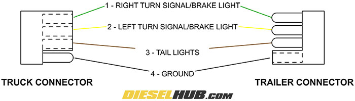
Typical 4 pin truck and trailer connector pinout diagram
Standard 6 Pin Trailer Connector
Pin # |
Function |
Common Wire Color(s) |
Min. Wire Size |
1 |
Common ground |
White |
12 AWG |
2 |
Electric trailer brakes |
Blue |
12 AWG |
3 |
Tail lights, license plate light, running lights |
Brown |
16 AWG |
4 |
12v+ auxiliary charging circuit |
Black/Red |
12 AWG |
5 |
Left hand turn signal, left hand brake light |
Yellow |
16 AWG |
6 |
Right hand turn signal, right hand brake light |
Green |
16 AWG |
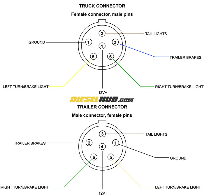
Typical 6 pin truck and trailer connector pinout diagram
Standard 7 Pin Blade Type Trailer Connector
Pin # |
Function |
Common Wire Color(s) |
Min. Wire Size |
1 |
Common ground |
White |
12 AWG |
2 |
Electric trailer brakes |
Blue |
12 AWG |
3 |
Tail lights, license plate light, running lights |
Brown |
16 AWG |
4 |
12v+ auxiliary charging circuit |
Black/Red |
12 AWG |
5 |
Left hand turn signal, left hand brake light |
Yellow |
16 AWG |
6 |
Right hand turn signal, right hand brake light |
Green |
16 AWG |
7 |
Backup lights |
Orange/Purple |
16 AWG |
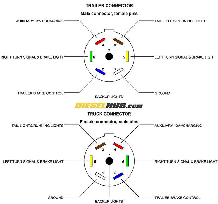
Typical 7 pin truck and trailer pinout diagram
Trailer Light Troubleshooting
Step 1 |
Check the connection between the truck and trailer |
• Clean any dirt or debris from both connectors and ensure that the trailer connector is inserted completely into the truck connector. A shot of WD-40 or dielectric lubricant into each of the connectors may help clear and clean the connectors. |
Step 2 |
If a single light is not working |
• Replace the bulb or light assembly, the most likely problem is that the bulb has burnt out. If this does not remedy the problem, continue to step 4. |
Step 3 |
If no lights are working, check the ground at the truck connector |
• Using a digital multimeter, check for continuity between the truck's ground pin and the chassis (probe the ground pin of the connector and a clean spot on the frame/bumper) |
• If the connector has a good ground, this is not the problem. |
||
• If the connector has no ground, the ground wire has been cut, disconnected, corroded, etc; find and repair as necessary. |
||
Step 4 |
Determine whether the problem is with the truck or the trailer |
• Disconnect the trailer connector from the truck. |
• Have a helper operate the light(s) that are not working, i.e. have someone depress the brake pedal, activate the turn signal, etc. |
||
• With a digital multimeter set to the proper range to read ~12v+ (or using a test light), probe the appropriate pin and a good ground (clean area on the frame, bumper, etc). The pin should read 12v+ when the corresponding light is activated from the truck. |
||
• If the appropriate pin reads ~12v+ with the switch/pedal engaged, the problem is with the trailer, not the truck. |
||
• If the pins are not providing power when they should, check for blown fuses and/or chafed wires along the frame. Refer to your owner's manual for information regarding specific fuse locations. |
||
Step 5 |
Troubleshoot the wiring in the trailer |
• If you have confirmed that the problem is not with the tow vehicle and verified that the connection between the truck and trailer is solid, the problem must be with the trailer. Check for chafed, exposed, or cut wires and loose electrical connectors along the trailer's wiring harness. Repair as necessary. |
Electric Trailer Brake Troubleshooting
Step 1 |
Check the connection between the truck and trailer |
• Clean any dirt or debris from both connectors and ensure that the trailer connector is inserted completely into the truck connector. A shot of WD-40 or dielectric lubricant into each of the connectors may help clear and clean the connectors. |
Step 2 |
Verify the trailer brake controller is functioning |
• Verify that the trailer brake controller is powering on. |
• Use a digital multimeter to probe the brake control pin on the truck connector (see diagrams above for 6 and 7 pin connectors). Ensure the multimeter has a good ground. |
||
• Have a second person press the brake pedal while you read the multimeter. The voltage supply to the trailer brake pin on the truck's connector should read a voltage that rises as the brake pedal is depressed further and further, and should read 0 volts when the pedal is not depressed. |
||
• If the brake control pin on the truck's connector reads 0 volts while the brake pedal is depressed, the problem is likely the brake controller and/or wiring between the controller and the truck's trailer connector. |
||
Step 3
|
Check the trailer brake wiring |
• Each individual trailer brake contains a magnet that engages the brakes with a force proportional to the voltage supplied by the brake controller. Each magnet has two wires coming out of the brake drum - 1 wire should be connected to the trailer brake control (often, but not always a blue wire) in the wiring harness while the other needs to be connected to a good ground (typically the trailer frame). |
• Check for loose splices and cut/chafed wires from the brake drums to the trailer connector. Repair as necessary. |
||
• Check for voltage to the brake magnets by probing the ground and positive supply splices to each individual magnet while the brake pedal is depressed. There should be a splice for each wire several inches behind the backing plate for each individual brake that can be probed. If no voltage is read with the brake pedal depressed, the problem is in the trailer wiring (ground or brake control supply voltage somewhere between the trailer connector and this splice). |
||
Step 4 |
Check the condition of the brake magnets |
• If the trailer is receiving power from the tow vehicle when the brake pedal is depressed and all wires are properly connected, the magnets in the trailer brakes may be worn - it's time for a brake job. You can visually inspect their condition by removing the brake drum; if they're visually worn and/or scarred, replace them. |