ZF 5 Speed Clutch Master and Slave Cylinder Part Numbers
Part Description |
Part Number(s) |
Remarks/Notes |
Clutch master cylinder (1987-1992 models) |
[1] |
|
Clutch master cylinder (1993 - 1997 models) |
||
Clutch slave cylinder (all models) |
||
Master-slave hydraulic hose (all models) |
Ford F5TZ-7A512-A |
|
Master-slave hydraulic fluid |
[2] |
[1] Master and slave cylinders can also be purchased as assemblies that include a new hose.
[2] Any DOT 3 brake fluid will suffice; Ford part number provided.
ZF 5 Speed Hydraulic Clutch System Bleeding Procedures
If you have not already performed the Heim Joint Mod for 1988 - 1997 Ford trucks, we highly recommend you consider the upgrade. It completely removes and eliminates the problematic plastic bushing found in the eye of the clutch master cylinder pushrod. This is a permanent, maintenance free fix for an extremely common problem associated with the ZF 5 speed manual transmission.
The following procedures outline the replacement and bleeding processes with the master cylinder and slave cylinder installed on the vehicle - for information on bench bleeding, see sub-topic "Bench Bleed Procedures" near bottom of page.
Important note - at no time should the master cylinder be operated until the slave cylinder is installed at the clutch fork. If the master cylinder is operated without the slave cylinder installed on the transmission it may be damaged.
Click any thumbnail image to view fullsize - fullsize images contain important details when applicable.

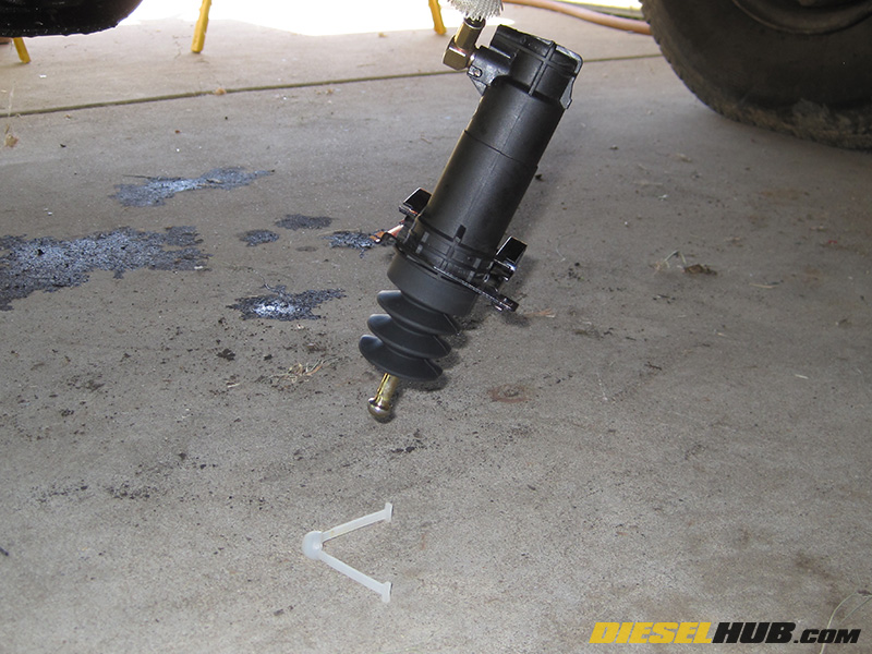
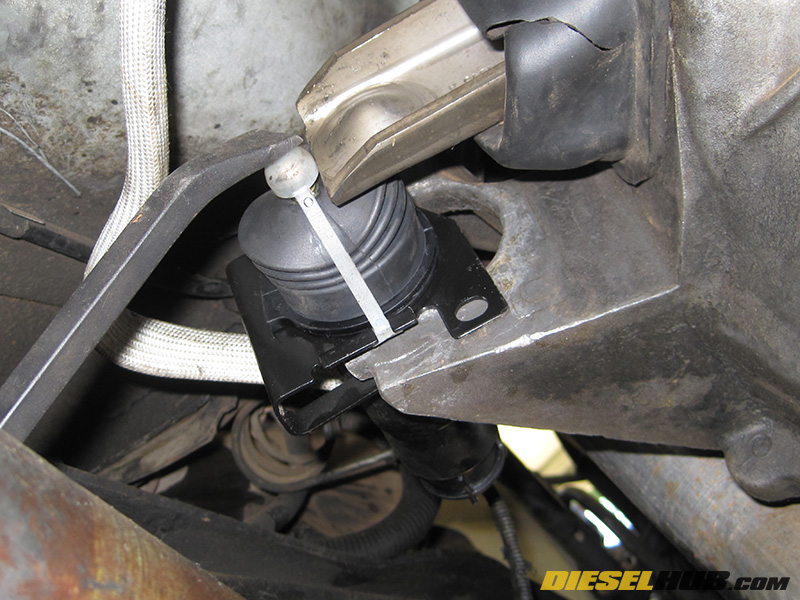
• Familiarize yourself with the components of the slave cylinder.
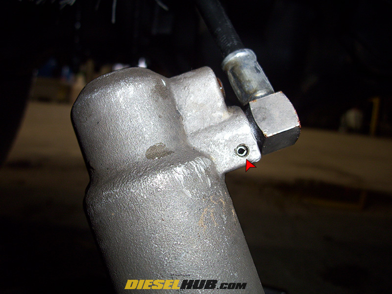
Hydraulic port: The hydraulic line attaches to the slave cylinder here by means of a small roll pin that is supplied with the part. A rubber o-ring type gasket is installed on the hydraulic line prior to installation.
Bleed screw: The bleed screw, located at the top of the cylinder on the side opposite the pushrod, uses a 5/32" Allen wrench.
Slave cylinder retention clip: This is a spring steel clip that holds the slave cylinder against the transmission. It is a very hard metal and the clip can be broke easily if pried on with too much force.
Slave cylinder pushrod strap: Do not lose or break this strap until the slave cylinder is installed! Without it, installation of the slave cylinder is extremely difficult. After installation, the plastic clip acts as a friction barrier between the metal pushrod and clutch fork.
Clutch Master Cylinder Removal
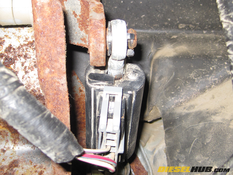
• If applicable, disconnect the electrical connector from the clutch pedal interlock switch that is attached to the master cylinder pushrod.
• Remove the eye of the pushrod from the clutch pedal swing arm pin using a screwdriver or similar tool to pry it off.
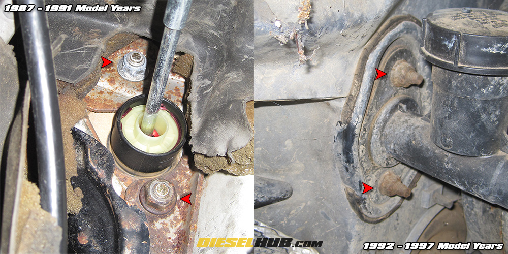
• Remove the two nuts securing the clutch master cylinder to the firewall with a 13mm socket. For 1987 to 1991 model years, the nuts will be accessible from within the cab. For 1992 to 1997 model years, the nuts will be accessible from the engine bay.
Note - on 92 to 97 model years, it may be easier to access the clutch master cylinder by first removing the section of intake tubing between the turbocharger inlet and air cleaner box.

• Trace the hydraulic line between the clutch master and slave cylinders. Disconnect any clips that secure the hydraulic line to the firewall, frame, or body so that it can be completely removed from the vehicle.
• Pull the master cylinder out from the firewall and let it hang loosely for the time being.
Clutch Slave Cylinder Removal
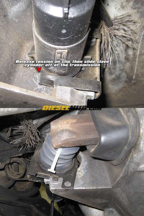
• The clutch slave cylinder is attached to the driver's side of the transmission via a metal clip.
• Remove the clutch slave cylinder by first releasing the clip on the backside, then pull/pry the cylinder off the mount (see fullsize image for details).
• Place a container beneath the slave cylinder to catch fluid.
• With the clutch slave cylinder removed from the transmission, press out the roll pin to separate the cylinder from the hydraulic line.
• Allow the hydraulic line to drain, then remove the clutch master cylinder and hydraulic line through the engine compartment.
• Disconnect the hydraulic line from the clutch master cylinder by driving out the roll pin.
Clutch Master & Slave Installation
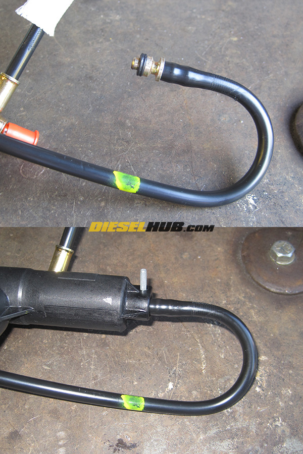
• With all the components removed from the vehicle, identify the clutch master cylinder side of the hydraulic line. Early trucks used a plastic line, while later trucks will have a metal line with a flexible braided section at one end. On plastic lines, the master cylinder side has a sharp "U" bend in it and a 180° fitting at the master cylinder end. On metal lines, the braided section is for the slave cylinder while the opposite end is designed for the master. The fittings are the same size on both ends and require the same gasket/roll pin. Do not re-use old gaskets and roll pins.
• Lightly grease and install the gasket on the hydraulic line, then install the line into the clutch master cylinder, securing it with the supplied 3/32" roll pin.
• Reinstall the master cylinder through the firewall, secure the nuts with a 13mm socket, and route the hydraulic line to the transmission.
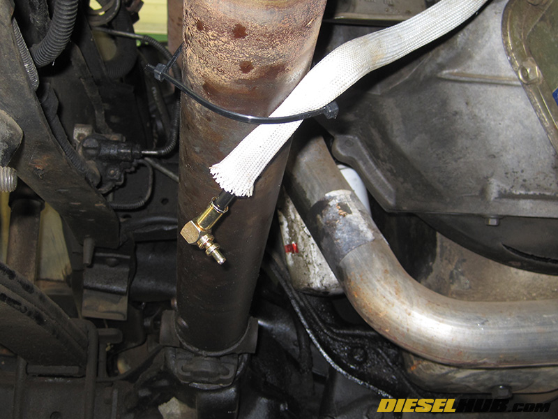
• Tape or zip tie the hydraulic hose to the front driveshaft (4x4) or frame (4x2) with the fitting facing downwards. Place a container under the hydraulic line fitting.
• Gravity bleed the hydraulic line - Fill the master cylinder with fluid and allow it to drain out the opposite end of the hydraulic line. Continue to keep the fluid reservoir full until fluid, but not air, runs out the end of the hydraulic line then cap it off. The supplied cap or a small vacuum cap works well. This is much easier with two people.
• From underneath the truck, install the slave cylinder. Lightly grease the gasket, install the gasket to the hydraulic line fitting, insert the hydraulic line into the port on the slave cylinder, and finally install the roll pin.
At this time, DO NOT operate the master cylinder or damage to the slave cylinder may occur!
• Carefully remove the plastic retaining clip from the cylinder after first depressing the pushrod. Do not break the plastic clip.
• Refill the clutch master cylinder fluid reservoir.
• From beneath the truck manually depress the slave cylinder piston completely with your hand, then release and allow it to extend on its own. Repeat this process while a second person maintains the fluid level in the clutch fluid reservoir. Do not let the reservoir run out of fluid or air will be re-introduced into the system.
• Repeat the pumping process until it becomes difficult to depress the slave cylinder manually.
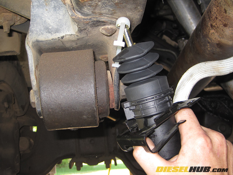
• Reinstall the slave cylinder pushrod retaining clip. This will be difficult since the slave cylinder becomes tough to depress once the cylinder is full of fluid. We accomplish this by installing the clip onto the tip of the pushrod, placing the pushrod into a hole/indentation of the frame, and applying force against it with one hand until the clip can be re-secured to the mounting bracket with our free hand.
• With the pushrod cylinder retracted and the retaining strap installed, install the slave cylinder back onto the transmission.
Tip - For most people, this is difficult the first time. Try sliding the slave cylinder into the mount on the transmission, then use a pry bar to further retract the pushrod and slide it into the clutch fork indentation. If done correctly, the slave cylinder will pop into place and the plastic retaining strap will be released.
Make sure the slave cylinder is correctly installed before proceeding.
• Reinstall the clutch master cylinder pushrod to the clutch swing arm under the dash.
ZF Clutch Master & Slave Bleeding Procedures
• Double check that the clutch master cylinder and slave cylinder are correctly installed. Verify that there are no leaks in the hydraulic line, and that the clutch fluid reservoir is filled to the fill line.
• Place a 5/32" Allen wrench into the bleed screw. Without opening the bleed screw, verify that the wrench is installed with sufficient room to open/close the bleeder. The bleed screw is opened by turning counterclockwise and closed by turning clockwise. However, if you're laying on your back underneath the transmission, the rotations are opposite.
• During the bleeding process, fluid is going to be ejected from the bleed screw and will make an oily mess if you do not first place a rag over the bleeder orifice.
• With the fluid reservoir cap/bladder installed and the bleed screw closed, depress the clutch pedal. Clutch operation should feel spongy and the clutch fork should move little, if at all - this is because air is trapped in the system.
Standard Bleed Procedures:
• Have one person depress the clutch pedal until it bottoms up. Once the clutch pedal has been fully depressed, a second person opens the bleed valve for 2-3 seconds, then closes it. Once the bleed screw is closed, allow the clutch pedal to return to the up position.
• Repeat the process, checking the clutch fluid reservoir level after every bleed cycle. Do not allow the fluid reservoir to drain completely. Do not allow the pedal to return to the up (non-depressed) position while the bleed valve is open - the system will take in air.
Alternative Bleed Procedures (for stubborn systems):
Occasionally, a stubborn system does not completely bleed with the standard procedures. We've identified the cause of this to be in the fact that a small amount of air can become trapped and/or sucked into the system when the pedal is held in the depressed position with the bleed screw open. The following method is slightly different and requires proper timing between the pedal and bleed screw operators.
• One person slowly depresses and holds the clutch pedal down. We do this on a three second basis. When the operator begins to depress the clutch pedal, he audibly counts "1". When the clutch pedal reaches the middle position, he counts "2". And when the clutch pedal is fully depressed, he counts "3". Be sure that the person beneath the truck can hear the counts.
• When the person operating the bleed screw hears "1", he cracks open the bleed screw. Shortly after he hears "2", he closes the bleed screw. When he hears "3", the bleed screw needs to be closed. At "3", as a safety measure, the clutch pedal operator holds the clutch in the fully depressed position until the second person confirms the bleed screw is closed. When it is confirmed that the bleed screw is closed, allow the pedal to return to its original position.
Note - the goal is to time it such that the bleed screw is closed just before the clutch pedal reaches full depression. If the bleed screw remains open at full depression, the system may start to suck in air as it loses pressure; this seems to be why the standard method does not always work.
• Repeat the process until the clutch pedal feel is firm and no air escapes when the bleed screw is cracked. After every other cycle, check and top off the clutch fluid level. Always be sure to replace the reservoir cap/bladder before operating the clutch pedal. If the fluid level becomes empty, the master cylinder will push air through the system and the process will need to be repeated.
With either procedure (or combination of the two), it typically takes us 10 to 15 cycles to fully bleed the system. It may take significantly more or significantly less cycles to completely bleed the system as there are many variables at play. Once you think the system is bled, drive the truck and check for smooth engagements in all gears. If there is grinding, the clutch pedal does not return to its top position, or engagements are tight, there is likely still air in the system. Repeat these procedures until the clutch functions normally.
Clutch Master and Slave Bench Bleeding Procedures
If you have both the master and slave cylinder removed from the vehicle, an alternative approach is to bench bleed the system. If you are bleeding a system on your own, this is the only viable method. If done properly, you will not have to perform any bleeding procedures with the master/slave cylinders installed on the vehicle.
• With the hose installed and properly secured between the master and slave cylinders, carefully fix the master cylinder upright in a vice.
Note - at no time during the bench bleeding process should you actuate the master cylinder pushrod; damage to the slave cylinder may occur.
• Fill the fluid reservoir on the master cylinder to the fill line, leaving the cap and bladder off. Place the slave cylinder in/over an oil catch can at an elevation lower than the master cylinder (so gravity will force fluid to flow from the master to the slave cylinder).
• Open the bleed screw on the slave cylinder and monitor the fluid level in the master cylinder reservoir. Do not allow the reservoir fluid level to completely drain.
• Once a steady stream of fluid (no air) begins to run out of the bleed screw orifice on the slave cylinder, completely close the bleed screw on the slave cylinder.
• Completely fill the fluid reservoir on the master cylinder, then release the plastic slave cylinder pushrod retaining strap without damaging it. As the slave cylinder pushrod extends, it will draw fluid from the master cylinder reservoir.
• Once the slave cylinder has fully extended, manually actuate the slave cylinder pushrod by pushing it in until it is fully retracted, then allowing it to spring back to its extended position. Repeat this process while maintaining the fluid level in the master cylinder reservoir until all of the air is purged out of the system. It should become increasingly difficult to operate the slave cylinder piston as the air is removed. Bubbles in the fluid reservoir indicate air being forced out of the system.
Note - you may wish to cover the fluid reservoir with a rag to prevent oil from spilling as you are manually actuating the slave cylinder piston.
• Once the system has been bled, manually retract the slave cylinder pushrod and reinstall the plastic retaining strap. Add/remove fluid from the master cylinder reservoir so that the level is at the max fill line, then install the bladder and cap.
• Install the master cylinder and slave cylinder per the aforementioned procedures.