The ZF 5 speed is a hydraulic "master and slave" system, meaning the only mechanical linkage in the system is the clutch pedal swing arm and there are no adjustments to compensate for wear in the pedal assembly. It is extremely common for the thin plastic bushings in the clutch pedal pivot shaft to wear, allowing the rod to literally grind away at the pedal assembly itself. The problem compounds the longer the pivot shaft is allowed to eat away at the metal holes in which it rests - eventually, you'll end up with an oval hole instead of a round one, requiring more extensive repairs or replacement of the entire assembly.
The problem is most prevalent on 1987 to 1991 model years as the clutch/brake pedal is made of cast aluminum, which wears faster and is more difficult to repair than the steel assembly found on 1992 to 1997 model years. After removing the clutch/brake pedal assembly (as outlined in the procedures below), inspect for excessive wear and replace the bushings or entire assembly as necessary to alleviate your clutch throw issues. We also highly recommend performing the Heim Joint Mod to eliminate concerns associated with the plastic clutch master cylinder rod eye bushing wearing.
Clutch Pedal Bushing Parts List
Part Description |
Part Number(s) |
Remarks/Notes |
Heim joint mod (pushrod bushing eliminator) |
[1] |
|
1987 - 1991 clutch & brake pedal bushing set |
--- |
|
1987 - 1991 clutch & brake pedal bracket assembly |
Ford FOTZ-2L252-B |
[2] |
1987 - 1997 clutch master cylinder pushrod bushing |
--- |
|
1987 - 1997 clutch rod swing arm |
[3] |
[1] Recommended modification, eliminates the failure-prone clutch master cylinder pushrod bushing and replaces it with a non-wearing rod end or "heim joint". This upgrade is optional, but is installed in the procedures below.
[2] Obsolete part no longer produced by Ford Motor Company nor any aftermarket manufacturer. Available second hand through dismantlers or NOS through obsolete part dealers. Becoming increasingly difficult to find.
[3] May be reused, however it is ideal to replace this part.
Clutch Pedal Bushing Replacement Procedures
The following procedures are applicable to 1987 - 1991 model year pickups. For later model years, please see: 1992 - 1997 Clutch Pedal Bushing Replacement
Click any thumbnail image to view fullsize
• Disconnect both negative battery cables.
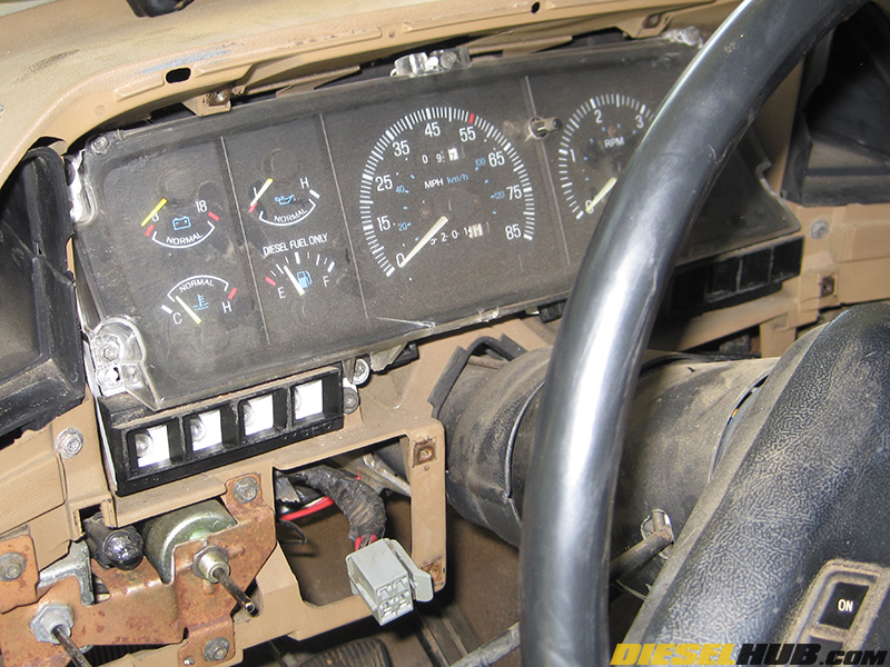
• The speedometer cable runs through the center of the pedal assembly on 1987 to 1991 model pickups, thus it needs to be disconnected from the gauge cluster.
• Remove the upper and lower trim from around the dash/gauge cluster. The trim pieces are held in place by various Torx T20/7mm socket screws. The knobs for the head lights and windshield wipers will also need to be removed.

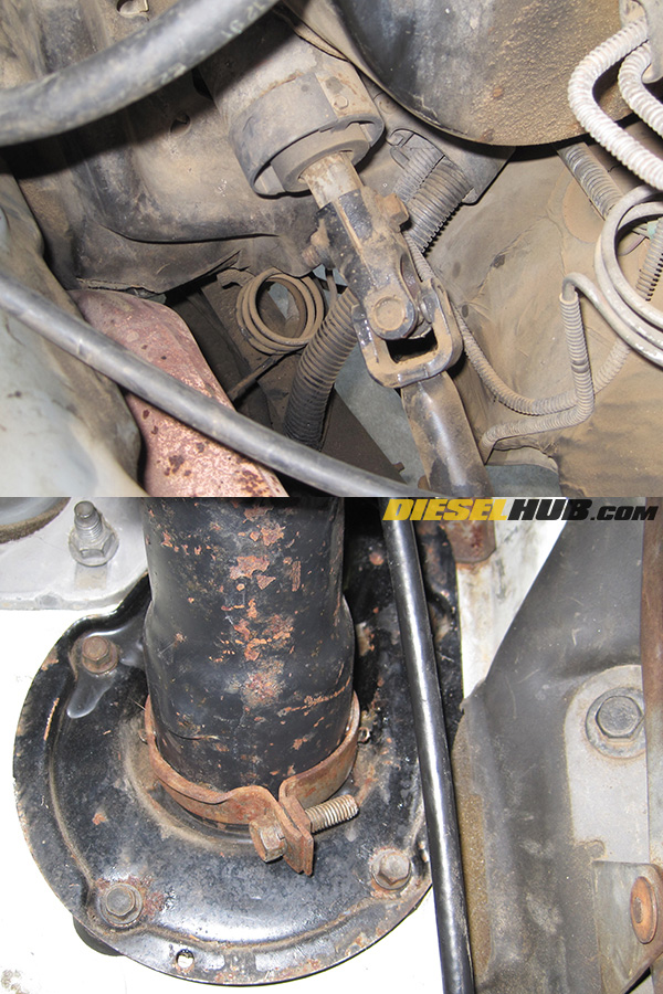
• Remove the speedometer cable from the transfer case tailhousing (transmission tailhousing for 2WD pickups). Using an 11mm socket, remove the nut at the base of the speedometer cable and then pull the tip of the cable straight out.
• From beneath the dash, gently pull the speedometer cable upwards into the cab 1 to 2 inches.

• Now that you have given the speedometer cable some slack, unbolt the gauge cluster from the dash (series of Torx screws).
• Pull the gauge cluster out as far as possible. To disconnect the speedometer cable, push in on the white tab while pulling the cable out of the rear of the gauge cluster. Pushing in unlocks the cable connector - when done correctly, the cable disconnects easily. Do no try to force the cable out; use the images at left as reference since you likely won't be able to see what you are doing.
• Disconnect the large electrical connectors from the left and right side of the gauge cluster, then set aside.
1987 - 1991 F-Series Steering Column Removal

• Remove and push aside any wiring that crosses below the steering column, as it will need to be removed. The amount of wiring in this region will vary from truck to truck; our brake controller wiring, for example, needed to be disconnected.
• Disconnect the large electrical connector beneath the steering column and push the wires aside and out of the way.
• From under the hood, remove the bolt that connects the steering column to the steering shaft (13mm socket).
• Separate the steering column from the steering shaft. This joint may be rather tight. After a quick shot of WD-40, we tapped the joint with a ball peen hammer while pulling away and it slipped off with relative ease.
• From in the cab, loosen the band around the base of the steering column (1/2" socket) and remove the five bolts securing the base of the steering column to the firewall (3/8" socket, see images for reference).
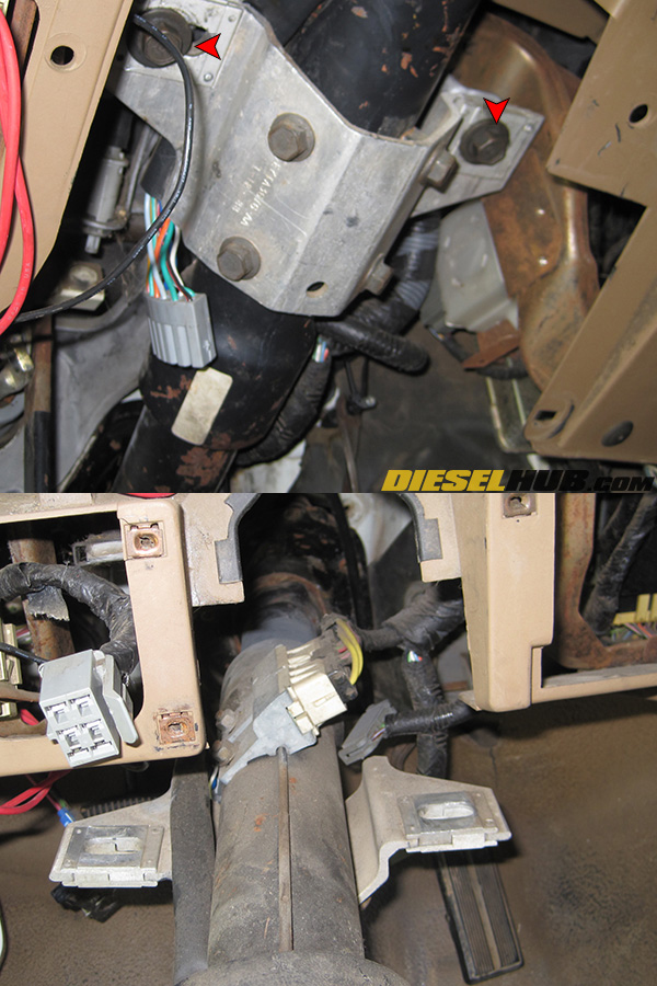
• Remove the pair of large bolts from the upper steering column bracket (14mm socket). It is not necessary to remove the four smaller bolts; only remove the two bolts referenced with red arrows in the image at left.
• Remove the steering column from the vehicle and store in a safe place.
1987 - 1991 F-Series Brake/Clutch Pedal Assembly Bracket Removal
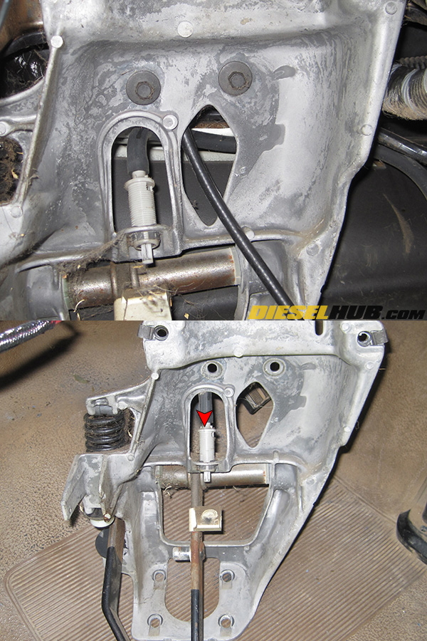
• Locate and remove the clutch master cylinder pushrod from the clutch rod swing arm. A flat head screwdriver is useful in prying the rod from the swing arm pin. If the plastic bushing inside the eye of the clutch master cylinder pushrod is worn or damaged, it will need to be replaced. You also may consider the "heim joint mod" in order to eliminate this bushing altogether.
• Depending on model year, the push rod may have a sensor attached to it - simply disconnect the connector and push aside, you do not have to remove the switch itself.

• Locate and remove the brake master cylinder push rod from the brake pedal. There is a red spring pin that needs to be removed (needle nose pliers work well), then the rod can be slid off of the mounting pin (be careful not to lose the bushings between the eye of the rod and the pedal itself). The brake light switch will also slide off; set it aside and out of the way.

• Remove the four nuts around the master cylinder push rod that secure the pedal assembly to the firewall (9/16" socket).
• From under the hood, carefully pull the master cylinder away from the firewall several inches and let it hang (see images for reference). There is no need to disconnect any lines, we're simply making enough room to remove the pedal assembly.
• Remove the two bolts located in the top of the pedal assembly (10mm socket), then remove the entire assembly away from the firewall while carefully guiding the speedometer cable through it.
• If the truck is equipped with cruise control, you'll need to disconnect the hose from the vacuum switch before removing the pedal assembly from the truck - this is easier with the assembly removed from the firewall and laying on the driver side floor board.
• With the pedal assembly on a bench, remove the 18mm nut on the clutch rod swing arm side of the assembly, then remove the clutch swing arm - it will be tight as splines are cut into the swing arm eye during assembly. Vice grips and a small pry bar make quick work of it.
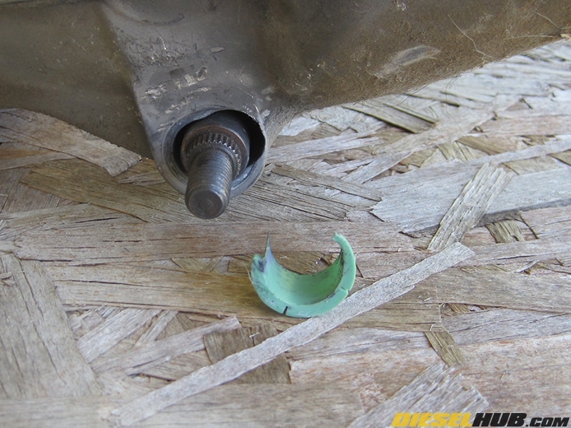
• This is an all to familiar sight and a worse case scenario - the bushing has been worn down completely and the rod has eaten away at the hole on the clutch swing arm side of the pedal assembly. In this case, we suggest replacing the entire assembly instead of trying to repair the soft cast aluminum.
1987 - 1991 ZF 5 Speed Clutch Pedal Bushing Replacement

• Release the clutch pedal spring tension with a pair of channel locks, then remove the spring from its lever arm - it is easier to replace the bushings with no spring tension.
• Loosen the 18mm nut on the clutch pedal side of the pivot rod.
• Pull the shaft out towards the clutch pedal side of the assembly.
• Install the new pedal bushings, reassembling in reverse order and using a liberal amount of grease on the bushings. Install the clutch pedal spring and tighten down the 18mm nut on the clutch pedal side of the shaft.
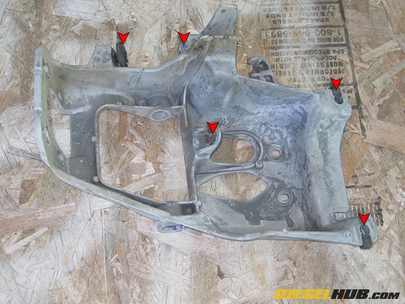
• If you are replacing the pedal assembly bracket (87 - 91 models), you'll need to transfer the threaded clips and rubber pads (see red arrows in fullsize image) to your new bracket.
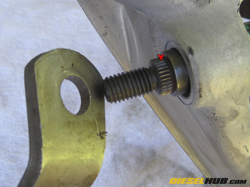
• Proper alignment of the clutch rod swing arm is imperative during re-installation. The swing arm comes from the factory without splines and they are cut by the teeth on the pivot shaft during installation. You may choose to replace the entire swing arm (Ford E7TZ-7A554-A ) or just cut new threads into the used swing arm, although each time new threads are cut, the strength of the joint is weakened. We highly recommend purchasing a new swing arm.
• Install the clutch swing arm and attach the 18mm nut, but do NOT tighten the nut - the swing arm should spin freely on the shaft at this point and should not be in contact with the splined section of the pivot shaft.
• Install the clutch/pedal assembly into the vehicle, re-install the steering column (use threadlocker on steering shaft joint bolt), wiring, dash, etc in the reverse manner they were removed.
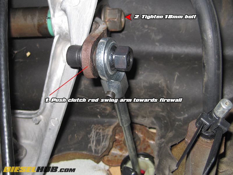
• The final step is to set the proper clutch swing arm position and tighten down the 18mm nut on the end of the pivot shaft. Install the master cylinder pushrod onto the clutch swing arm (if you have performed the heim joint modification, install the bolt that connects the swing arm to the pushrod).
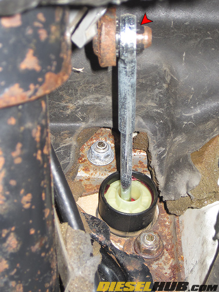
• Push the swing arm forward towards the firewall (counterclockwise if looking at the swing arm from the passenger side) until all slack is removed in the throw of the master cylinder pushrod, then tighten down the 18mm nut while keeping tension (refer to fullsize image). After operating the clutch pedal several times, tighten this nut once more. We also recommend tightening again after approximately a week of normal driving.