6.0L Power Stroke ICP Sensor Parts List
Part Description |
Part Number(s) |
Remarks/Notes |
ICP sensor, 2003 - early 2004 |
[1] |
|
ICP sensor, late 2004+ |
[2] |
|
ICP sensor connector pigtail |
[3] |
|
IRP valve service kit |
[4] |
[1] All 2003 and early build 2004 models with ICP located beneath the turbocharger through the HPOP cover.
[2] Late 2004 and up models with ICP located through the passenger side valve cover.
[3] Faulty connectors can emulate the symtoms of a bad ICP sensor; for good measure, we always recommend replacing the connector when replacing the ICP sensor.
[4] Only necessary if IPR valve is found to be leaking and requires service (the IPR valve is located next to the ICP sensor on 2003 and early 2004 models)
6.0L Power Stroke ICP Sensor Function, Diagnostics, & Troubleshooting
The ICP (injector control pressure) sensor measures the actual pressure in the high pressure oil circuit. Recall that the 6.0L Power Stroke utilizes an HEUI (hydraulic electric unit injector) system in which pressurized engine oil is used to create the final fuel injection pressure in lieu of a high pressure fuel/injection pump. The oil pressure in the high pressure circuit can exceed 3,000 psi, creating a fuel injection pressure of up to 26,000 psi.
The ICP sensor reading is used, amongst other things, to control the position of the IPR valve, which regulates the pressure of engine oil in the high pressure system. As the system's watchdog, ICP is monitored and compared to a desired value for a particular set or combination of operating parameters (engine load, speed, etc). The IPR valve is than commanded open/closed as necessary to chase the desired ICP value.
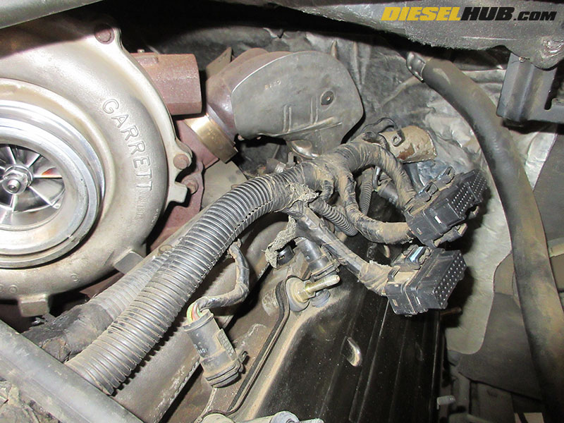
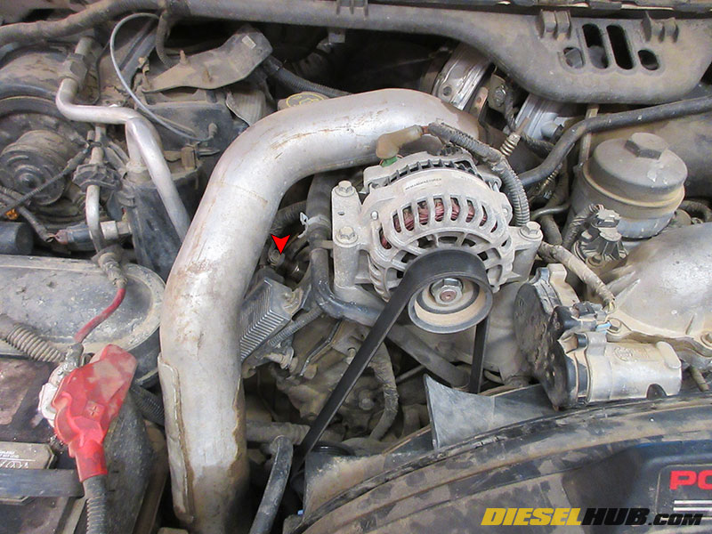
On 2003 and early 2004 model year 6.0L Power Stroke engines, the ICP sensor is located behind the turbocharger and beneath the turbocharger up-pipe collector (turbine inlet), fastened through the high pressure oil pump (HPOP) cover next to the IPR valve. Starting mid-year in 2004, the ICP sensor was moved to the passenger side valve cover near the glow plug controller. Replacing the ICP sensor is therefore somewhat labor intensive on the early engines, and very simple for 2004 to 2007 model years. ICP sensor problems are also more common on early engines as the sensor and its connector get baked by the turbocharger and up-pipe collector.
ICP Sensor Diagnostics & DTCs
Symptoms of a faulty or failed ICP sensor typically include:
• Intermittent engine stutter and/or rough idle
• Hard start, long crank condition
• No start condition
• Engine stalling
• Overall reduced performance
Diagnosing an ICP sensor is not terribly difficult with the correct tools, but it is important to recall that the ICP sensor is just one part of a complex system; just because an ICP reading is low, high, or abnormal, does not necessarily mean that the ICP sensor is the problem. An IPR valve fault, weak HPOP, or even severe internal leak in the high pressure oil circuit can also cause an abnormal or low pressure condition, setting a DTC relating to injection control pressure.
With an appropriate scantool (even some aftermarket tuners/programmers feature this functionality), monitor the injection control pressure, injection control pressure desired, and injection pressure regulator duty cycle PIDs. Compare with the following values:
PID |
Value, Engine Cranking |
Value, Engine Idling |
Notes |
ICP |
minimum 500 psi |
600 - 800 psi |
Typically between 800 and 2,000 psi before engine starts. |
ICP desired |
--- |
--- |
Value should be reasonably close to actual ICP with engine running. |
IPR duty cycle |
up to 84% |
~ 30% |
IPR duty cycle should start at 15% with the key "ON" and engine "OFF". |
Unplugging the ICP sensor defaults the reading to 750 psi. In the event of a no start, hard start, or rough running condition, attempt to start the engine with the ICP sensor unplugged. If the engine starts normally and runs smoothly, replace the ICP sensor and ICP sensor pigtail. If unplugging the ICP sensor does nothing, further diagnostics are required to find the actual problem. The following DTCs are related to the ICP sensor, but the ICP sensor itself does not have to experience a fault for most of them to be set:
DTC |
Description |
Notes |
P2284 |
ICP sensor range/performance |
An abnormal reading was detected outside of the normal range of the sensor (COMMON) |
P2285 |
ICP sensor circuit low |
Oil pressure in the high pressure circuit was found to be relatively low for a given set of operating parameters (VERY COMMON) |
P2286 |
ICP sensor circuit high |
Oil pressure in the high pressure circuit was found to be relatively high for a given set of operating parameters (LESS COMMON) |
P2287 |
ICP sensor circuit intermittent |
Check ICP sensor connector/circuit for chaffing; sensor signal is intermittently lost/interrupted (VERY COMMON) |
P2288 |
ICP too high |
Oil pressure in the high pressure circuit was found to be excessively high (LESS COMMON) |
P2289 |
ICP too high w/ engine off |
Oil pressure in the high pressure circuit was found to be excessively high with the key on, engine off (LESS COMMON) |
P2290 |
ICP too low |
Oil pressure in the high pressure circuit was found to be excessively low (LESS COMMON) |
P2291 |
ICP too low, engine cranking |
Oil pressure in the high pressure circuit was found to be excessively low while cranking engine (COMMON) |
Keep in mind ICP sensor DTCs are set if at any moment there is an abnormality. If an engine runs flawlessly but a DTC is set, clear the code and see if it returns. It is not uncommon for an occasional fluke condition to set a DTC, but if the DTC is continuously set the problem should be addressed.
How to Replace the ICP Sensor on a 2003 - Early 2004 6.0L Power Stroke
Click any thumbnail to view fullsize, detailed image

• Disconnect both negative battery cables.
• Drain approximately 3 gallons of engine coolant from the radiator into clean containers so that it can be reused. The drain valve is located on the bottom of the radiator on the driver side.
• Disconnect the (2) coolant lines attaching at the top of the degas tank and the (1) large coolant hose attaching at the bottom.

• Remove the (2) bolts securing the degas tank with an 8 mm socket, then remove the tank and set aside.
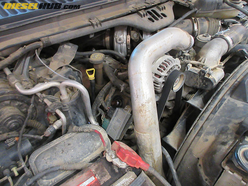
• Remove the intake tubing from the turbocharger inlet to the air filter.
• Remove the FICM and FICM mounting bracket (if necessary, see 6.0L Power Stroke FICM removal for specific instructions).
• Remove the ground from the rearmost intake manifold stud on the driver side (small o-ring terminal).
• Remove each fuel injector connector on the driver side bank (push metal clip into connector then pull up, or remove the metal clip altogether and pull up).
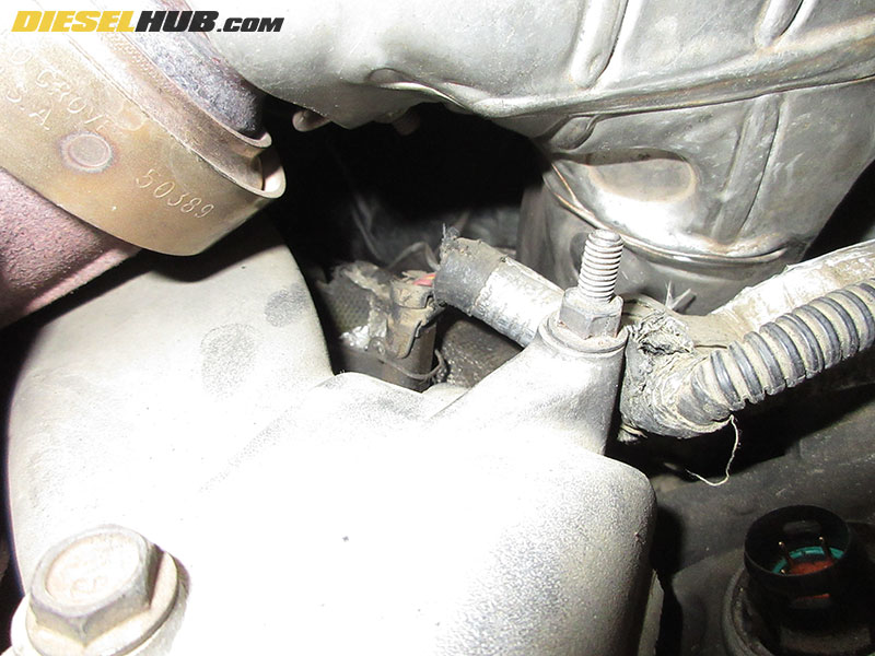
• Reach under the turbocharger up-pipe collector and unplug the IPR valve and ICP sensor connectors.
• Pull the entire driver side electrical harness toward the front of the engine out of the way. There may be several locations where the connector attaches to the valve cover using small snap clips.

• Remove the rearmost intake manifold bolt with a 10 mm deep socket (where ground terminal was previously connected). This will make it significantly easier to reach the ICP sensor.
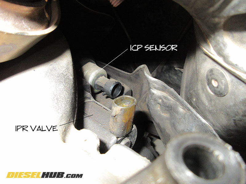
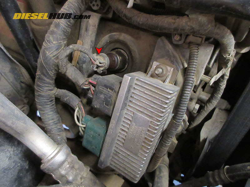
• Locate the ICP sensor below the turbocharger up-pipe collector.
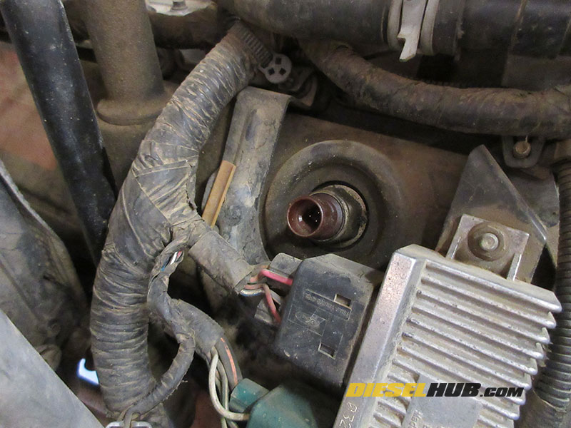
• Remove the ICP sensor with a 27 mm deep socket.
Note - access is limited; you may wish to remove the IPR valve to make room to reach the ICP sensor. If the IPR is removed, use service kit Ford 3C3Z-9H529-A to replace the IPR valve o-rings and mesh screen before reinstalling.
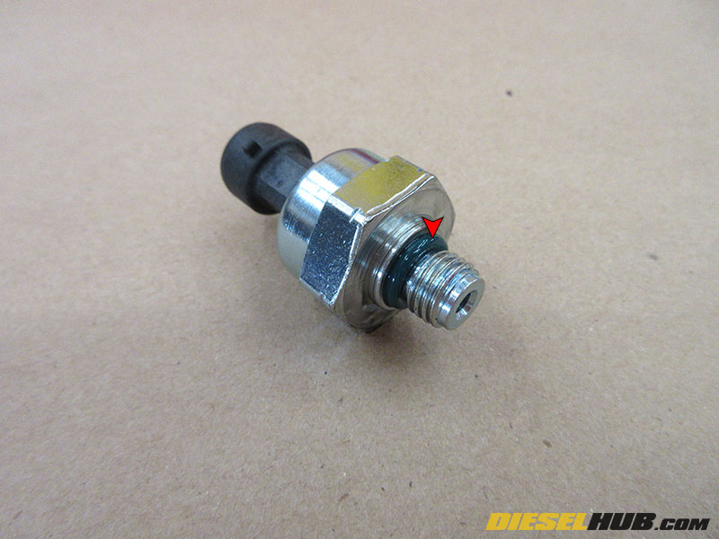
• Lubricate the o-ring on the new ICP sensor with clean engine oil. Install the ICP sensor in reverse order. Torque sensor to 106 in-lbs.
• See ICP sensor connector replacement below; we highly recommend replacing the connector when the sensor is replaced.
• If removed, torque IPR valve to 37 ft-lbs and rear intake manifold to 96 in-lbs.
How to Replace the ICP Sensor on a 2004 - 2007 6.0L Power Stroke
• Disconnect both negative battery cables.
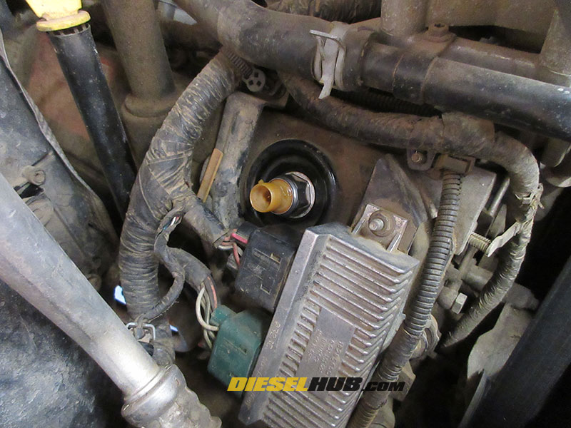
• Locate the ICP sensor on the passenger side valve cover just above the glow plug controller connectors.
• Disconnect the hot side intercooler tube from the turbocharger compressor outlet and position it out of the way so that the ICP sensor can be readily accessed.
• Disconnect the ICP sensor connector.

• Inspect the condition of the ICP sensor connector. If connector condition is acceptable, clean it with an appropriate connector cleaner (recommend CRC QD electronic cleaner). Do not attempt to clean the sensor with a harsh solvent such as brake cleaner, as it will damage the connector shell and seal. If the connector is damaged, the terminals are loose, or it is otherwise degrading from oil/heat exposure, a new connector pigtail should be spliced in place; see instructions in section below.
• Remove the ICP sensor with a 27 mm deep socket.
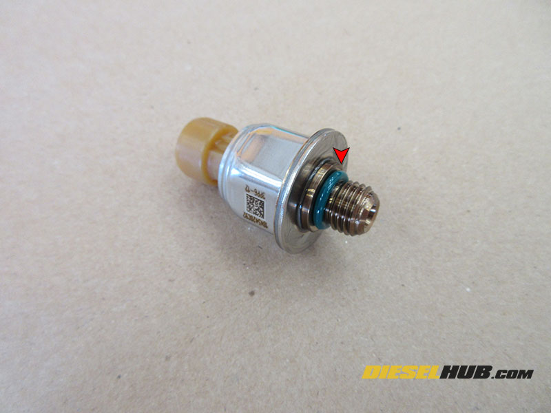
• Lubricate the o-ring on the replacement ICP sensor with clean engine oil.
• Install new ICP sensor; torque to 108 in lbs.
• Reinstall ICP sensor connector, intercooler tube, and negative battery cables.
6.0L Power Stroke ICP Sensor Connector Replacement
Replacing the ICP connector is almost always recommended on 2003 and early 2004 6.0L Power Strokes when the ICP sensor is replaced because the harness tends to get baked by the turbocharger and up-pipe collector, both of which generate a tremendous amount of heat. This, combined with the oil that often soaks the connector when an ICP sensor leaks, rapidly degrades the connector and compromises its integrity. Connector failures are less common on 2004 to 2007 model year engines where the sensor is located through the passenger side valve cover. However, the connector should always be inspected and replaced as necessary. It is not uncommon for ICP faults to be caused by a bad connector and not the sensor itself. The connector pigtail and splice kit is Ford p/n 5C3Z-12224-A.
• Begin by removing the factory wire loom and insulating sleeve(s) to expose the wires. Any damaged wire loom should be removed from the harness and replaced as necessary.
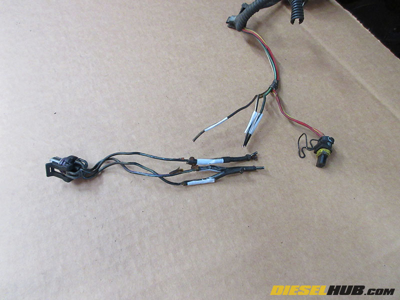
• The replacement pigtail wires are not color coded to the factory wiring harness. Therefore, you will need to mark/number the wires prior to splicing so that they can be matched accordingly. Here, we've numbered the wires on either side of the splice before cutting.
Note - do not trim the factory harness more than necessary; use pigtail length as a guide. Since this connector is often replaced more than once, you may wish to trim the pigtail and cut less out of the wiring harness.
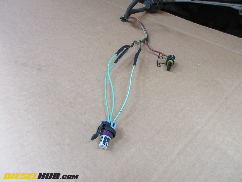
• Using the features of the old connector (it is a 3 wire non-symmetrical connector), match the appropriate wires on the replacement pigtails with the numbered harness wires.
• Slide heat shrink tubing over the pigtail leads, then crimp the new connector to the harness. Double and triple check that the wires are being crimped correctly.
• Slide the heat shrink tubing over the butt splices and activate with a heat gun to create a secure connection.
• Replace the wire loom, sleeving, and heat shielding as necessary.
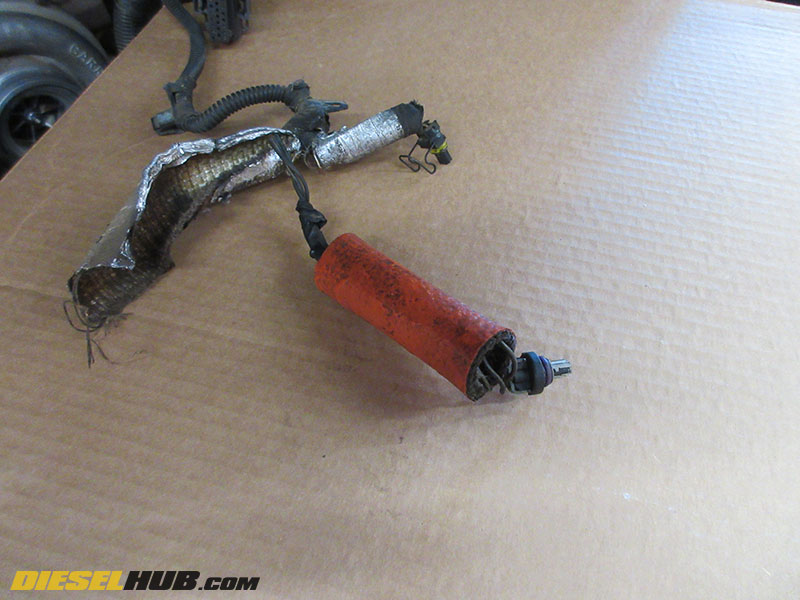
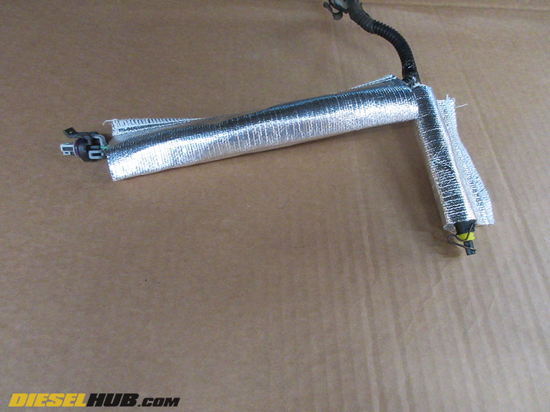
• Here, we've covered the ICP sensor and IPR valve connector wires with fiberglass insulation followed by a radiant heat shield. The radiant heat shield was left long so that it could be slid over the connectors themselves after installation.
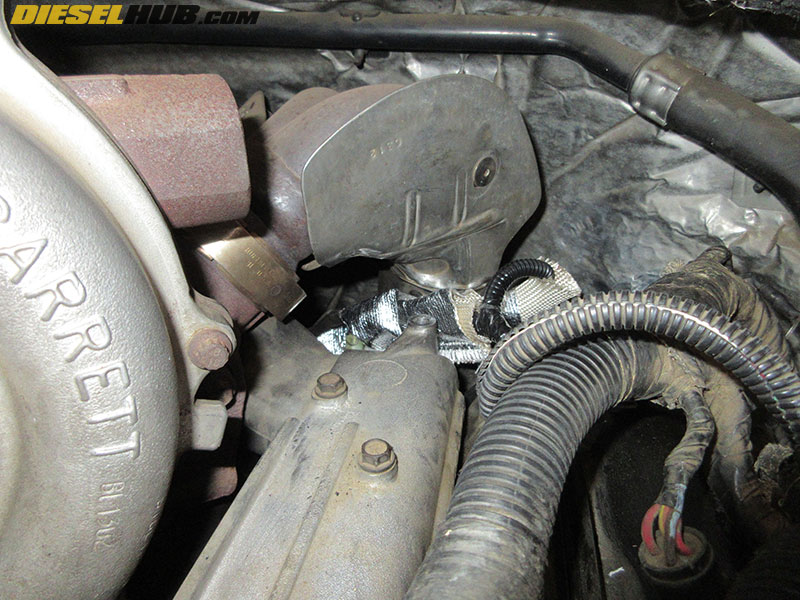
• Reinstall the ICP sensor and IPR valve connectors and ensure the harness is not touching the turbocharger up-pipe connector.