Valve lash refers to the clearance, generally hundredths or thousandths of an inch, between the tip of a rocker arm and the corresponding valve stem. Adjusting valve lash is necessary on engines featuring solid lifters, like the 12v Cummins, to compensate for normal wear. By design, solid lifters, unlike hydraulic lifters, have no inherent mode of self-adjusting to compensate for wear at the contact points between the valve stem and rocker arm nor the rocker arm and pushrod.
Valve lash that is set incorrectly may ultimately cause premature wear and/or damage to one or more valvetrain components. Cummins recommends adjusting the valve lash on 6BT (12v) engines every 24,000 miles or 24 months, whichever comes first. On later ISB models (24v), the valve lash is to be adjusted at significantly higher 150,000 mile intervals. The procedures below are based on a 5.9L 12v Cummins turbodiesel, however the premise is the same for later 5.9L ISB engines.
In addition to standard hand tools (socket/wrench set), this process requires a feeler gauge and engine barring tool. We highly recommend OTC 7471A, which is specifically designed for 5.9L Cummins engines. This tool will allow the engine to be rotated manually by the flywheel/flexplate using a 1/2" drive ratchet.
5.9L Cummins 6BT Valve Lash Adjustment Procedures
Click any thumbnail to view fullsize, detailed image
• Disconnect both negative battery cables.
• If applicable, remove the aluminum valve cover plate with a 19 mm socket or wrench.
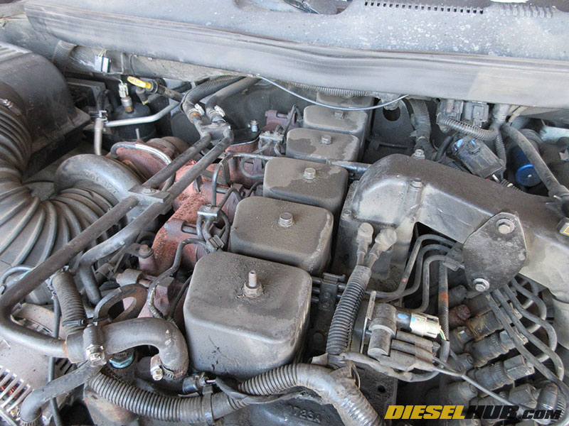
• Use compressed air to clean around each valve cover, blowing off any dust, dirt, and/or debris that could fall into the cylinder head when the valve cover is removed.
• Remove each individual valve cover using a 15 mm socket or wrench. If a valve cover sticks to the cylinder head, gently tap the side of it using a plastic dead blow hammer until it is freed; do not attempt to pry the valve covers off the cylinder head.
• On 1st gen trucks, remove the intake cross-over pipe.

• Remove the plastic plug from the bellhousing on the passenger side of the engine. The plug is visible by looking at the bellhousing from the front of the engine, not from looking at the rear of the engine (refer to image for details).
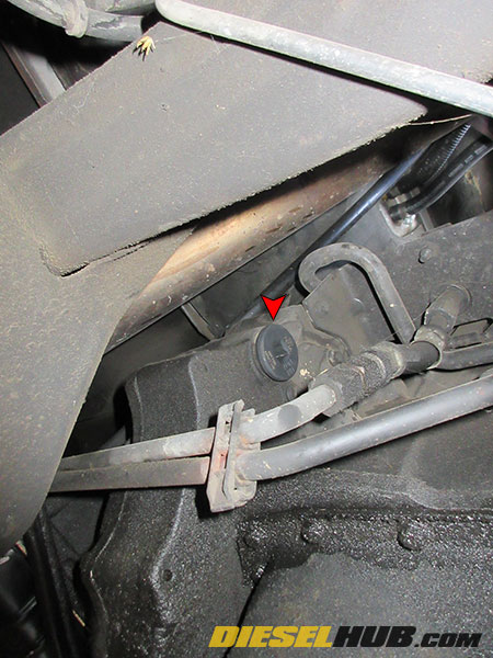
• Insert the barring socket into hole in the bellhousing and attach a 1/2" drive ratchet. From this point there are two methods for finding the appropriate camshaft position to begin adjusting the valve clearance.
Cylinder 1 TDC Method
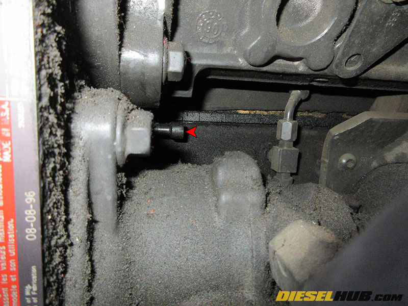
• Locate the timing pin on the back of the front cover, below the injection pump on the drivers side of the engine (it is difficult to see, you will need to feel for it). Refer to the image at left for details.

• Rotate the engine using the barring socket until the number 1 (front-most) exhaust valve closes, then continue to rotate the engine until the timing pin can be inserted into the camshaft gear (approximately 90 degrees of crankshaft rotation). Do NOT attempt to rotate the engine while the timing pin is engaged - it WILL break off in the front cover.

• Once the timing pin is in place, cylinder 1 is at top dead center (TDC).
• Insert a 0.020 inch feeler gauge between the tip of the rocker arm and the tip of the exhaust valve for cylinder 1. Move the feeler gauge back and forth - if there is some restriction, i.e. the feeler gauge contacts the valve/rocker arm, then no adjustment is needed. If the feeler gauge slides back-and-forth freely, loosen the adjustment locknut and tighten the adjustment screw until the proper clearance is achieved. Tighten the locknut while holding the adjustment screw in place, then take another reading with the feeler gauge to ensure the adjustment screw did not move while the locknut was being torqued down. Torque locknut to 18 ft-lbs (a crows foot is useful for this).
• Repeat the aforementioned step for the cylinder 1 intake valve using a 0.010 inch feeler gauge.
• Continue to adjust the following valves:
Cylinder 1 intake and exhaust valves
Cylinder 2 intake valve only
Cylinder 3 exhaust valve only
Cylinder 4 intake valve only
Cylinder 5 exhaust valve only
• Once the valves on these cylinders have been adjusted, ensure that the timing pin has been retracted from the camshaft gear and use the barring socket to rotate the engine counter clockwise 360 degrees (crankshaft makes 1 full rotation).
• Adjust the following valves:
Cylinder 2 exhaust valve
Cylinder 3 intake valve
Cylinder 4 exhaust valve
Cylinder 5 intake valve
Cylinder 6
intake and exhaust valve
Before loosening any locknut, wiggle the rocker arm to ensure there is no restriction. If the rocker arm is in contact with a valve it will not move and this indicates that the engine needs to be rotated before adjusting the valve. There can be no contact between a valve stem and rocker arm before adjusting the valve lash, all pressure needs to be relieved to indicate that the valve is seated.
Quick Valve Lash Adjustment Method
Note - requires a fundamental understanding of valve train timing.
• As in the previous method, use the engine barring tool to rotate the engine. The direction in which the engine is rotated is not important so long as you continue to rotate the engine in that direction until all valves are adjusted. Going from clockwise to counter-clockwise and visa versa will only double your work.
• Watch the intake and exhaust valves of all cylinders. When a valve closes completely and the pushrod is at the end of its downward stroke make the appropriate adjustment (0.020 inch for exhaust valves and 0.010 inch for intake valves). Wiggle the rocker arm to ensure that it is not in contact with the valve before loosening the locknut. Generally, the crankshaft needs to rotate several degrees beyond the point that the valve closes to ensure that the pushrod is at the bottom of its stroke.
• Repeat until all valves are adjusted, keeping track of which valves have already been adjusted. This method does not require engaging the timing pin and in some instances is much faster and may require rotating the engine less.
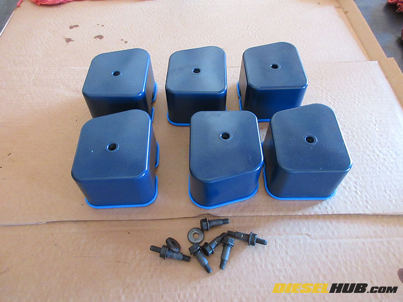
• Regardless of method used, reinstall the valve covers in reverse order once the clearance has been inspected and adjusted as necessary for all intake and exhaust valves. Valve cover gaskets are reusable but should be replaced if they are cracked, deteriorating, or there are signs of an oil leak. Torque valve cover bolts to 18 ft-lbs.
Ensure that the barring tool is removed from the bellhousing, the bellhousing plug is reinstalled, and the timing pin is NOT engaged before attempting to start the engine.