
The 6.7 liter Power Stroke is the first diesel engine designed, developed, and manufactured in-house by Ford Motor Company for pickup and chassis cab truck applications. Introduced to the Ford Super Duty platform (F-250, F-350, F-450, F-550) for the 2011 model year, it replaced the short-lived 6.4 liter Power Stroke produced by International-Navistar and marked the end of a decades long relationship between the two companies.
Ford's strategic decision to dissolve its relationship with International-Navistar, whom had supplied Ford Motor Company with diesel engines for the pickup truck segment since 1983, was based on a number of factors that included at least one large scale lawsuit over warranty claim responsibilities.
The 6.7 Power Stroke was internally codenamed "Scorpion" through its developmental stages. The nickname was derived from the unique shape and structure of the turbocharger arrangement, which feeds exhaust gases to the centrally mounted turbocharger from the top of the engine valley while the intake ports are positioned on the lower sides of the cylinder heads where, traditionally, the exhaust manifolds would be found.
Engine Features
Architecture
The 6.7 Power Stroke diesel is a standard 90 degree V-8 engine with a compacted graphite iron (CGI) engine block and aluminum cylinder heads. Its exhaust and intake manifold design is unique in that the flows are reversed; the intake ports are located on the outer deck of the cylinder head (closest to the fender wells) and the exhaust ports exit into the engine valley where the turbocharger is mounted. This design increases thermal efficiency by providing a shortened, direct path to the turbocharger turbine where the total heat dissipated is reduced and exhaust gas energy is conserved.
Fuel System
The 6.7L Power Stroke diesel employs a high pressure common rail fuel injection system. A Bosch CP4 injection pump produces up to 36,000 psi of injection pressure through Piezoelectric fuel injectors. The injection pump is fed by an electric lift pump that provides up to three times the required fuel flowrate to provide critical lubrication and cooling to the injection pump; unused diesel fuel is returned to the fuel tank in a continuous loop.
Two fuel filtration units are employed to ensure fuel is clean and free of water before entering the injection pump. The primary fuel filter captures particles down to 10 microns and is located in the diesel fuel conditioning module (DFCM), which also contains the fuel-water separator and is either frame mounted or mounted near the fuel tank (exact position depends on chassis and fuel tank type). The secondary fuel filter is mounted beneath the hood near the firewall on the driver side; it filters particles down to 4 microns. On 2011 to 2019 model year trucks, the fuel lift pump (low pressure fuel pump) is incorporated into the DFCM. On later model year vehicles, the fuel lift pump is located in the fuel tank.
All model year 6.7L Power Stroke diesels are certified to run on biodiesel blends up to B20 (20% biodiesel, renewable, or biomass diesel and 80% conventional petroleum diesel fuel). Operating the engine repeatedly on more concentrated biodiesel blends or pure biodiesel is not advised as fuel system damage may occur. Additionally, it is noteworthy that biodiesel and biodiesel blends degrade more rapidly that petroleum diesel and thus such fuels should not be stored in fuel tanks for extended periods of time (Ford suggests flushing biodiesel out fuel lines by filling and running vehicle with regular diesel if vehicle is to be stored for more than 1 month).
Turbocharger System
Although several different turbocharger configurations (and models) have been employed in the 6.7L Power Stroke engine platform, they all feature an air-to-water charge air cooler (intercooler) and some form of variable geometry turbocharger. The first generation 6.7 diesels (2011 - 2014) featured a unique single sequential "DualBoost" turbocharger. The single sequential design uses a pair of separately sized compressors mounted to a common shaft with a single turbine, allowing for performance characteristics similar to a twin turbo system but in the packaging of a single unit. Later engine generations would receive more traditional Garrett variable geometry turbochargers, likely due to the sequential turbos added expense and inferior reliability.
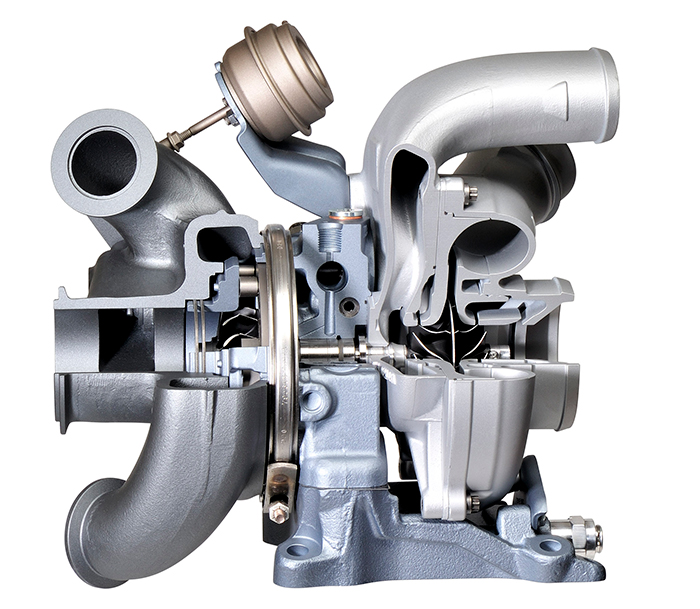
Image courtesy Ford Motor Company
An air-to-water intercooler utilizes engine coolant in the secondary cooling system circuit (see cooling system subsection below) to remove heat from the intake air charge in lieu of the traditional air-to-air intercooler systems found on previous Power Stroke engine models. In terms of heat transfer, water is a significantly more effective working fluid than air and thus the 6.7L Power Stroke's air-to-water charge air cooler is more efficient in removing heat from the air charge and reducing intake air temperatures.
Cooling System
The 6.7L Power Stroke diesel utilizes two separate cooling systems, each with its own radiator, degas bottle, thermostats, and belt driven water pump. The primary (high temperature) cooling system radiator is mounted behind (closer to the engine) the secondary (low temperature) cooling system radiator as the secondary system operates at a significantly lower temperature than the primary and is thus given priority to airflow through the grille.
2011 - 2014 Model Year Cooling System
The primary cooling system provides engine coolant to the engine block, cylinder heads, engine oil cooler, turbocharger, first half of the EGR cooler, and the heater core. A dual thermostat assembly with two separate thermostatic mechanisms that operate at different opening temperatures controls coolant flow through the primary cooling system. The first thermostatic mechanism opens at 194° F (90° C) while maximum coolant flow is achieved when the second mechanism opens at 201° F (94° C). Figure 2 below describes coolant flow in the primary cooling system circuit.
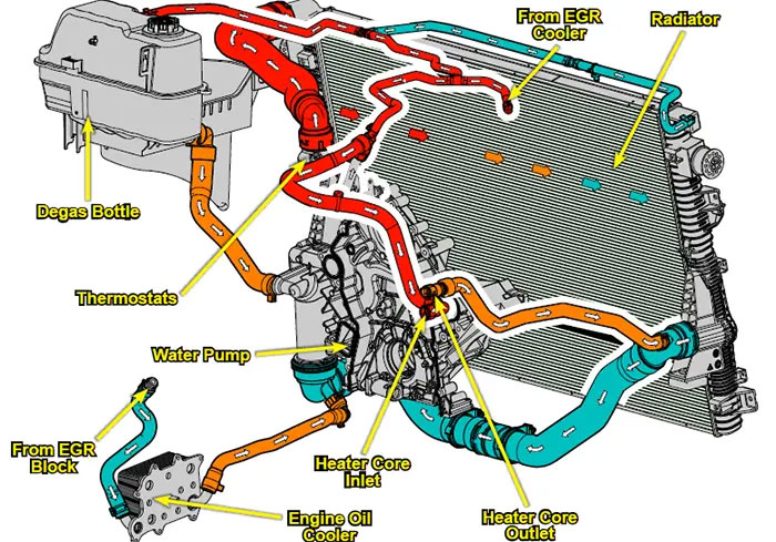
Image courtesy Ford Motor Company
The secondary cooling system provides coolant to the charge-air-cooler, fuel cooler, second half of the EGR cooler, and transmission oil cooler. The secondary radiator has two outlets, one on each side of the radiator, each controlled by a thermostat. The passenger side outlet is controlled by a 140° F thermostat and provides coolant to the EGR cooler and transmission oil cooler. Coolant that exits this outlet only circulates through the top half of the radiator. The driver side outlet, positioned closer to the bottom of the radiator, is controlled by a 113° F thermostat and provides coolant to the charge-air-cooler and diesel fuel cooler. Coolant that exits this outlet circulates through the top and bottom halves of the radiator and is this moderately lower in temperature than that exiting the passenger side outlet (the charge-air-cooler and fuel cooler require lower coolant temperatures than the EGR and transmission oil coolers). Figure 3 below describes coolant flow in the secondary cooling system circuit.
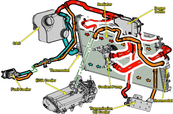
Image courtesy Ford Motor Company
2015 - 2027 Model year Cooling System
For the 2015 model year, the cooling system was modified so that both EGR coolant circuits were fed by the primary cooling system, reducing heat loads on the secondary cooling system and eliminating the dual thermostat radiator design. The 2020 6.7 Power Stroke update revised the cooling system yet again, this time removing the transmission cooler from the secondary cooling system and feeding it through the primary cooling system circuit. On 2020 and newer model year engines, the secondary cooling system only provides engine coolant to the air-to-water charge air cooler and the diesel fuel cooler.
Emissions System
The 6.7 Power Stroke diesel features a series of sophisticated emissions control systems, including advanced exhaust aftertreatment solutions. It is the first engine in the Power Stroke diesel family to require a selective catalytic reduction (SCR) system to reduce NOx emissions and meet emissions regulations at both the Federal and State levels. Figure 4 below outlines the arrangement of each component in the exhaust aftertreatment system.
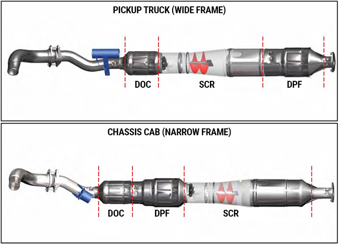
Image courtesy Ford Motor Company
Exhaust Gas Recirculation (EGR)
Exhaust gas recirculation is the first step in reducing emissions of nitrous oxides (NOx). By cooling and reintroducing a metered amount of exhaust gases into the intake air charge, combustion temperatures are reduced and NOx emissions are decreased substantially. The EGR cooler is mounted above the passenger side valve cover and features a two stage cooling circuit. While early engines (2011 - 2014) relied on the primary cooling system for the first stage of cooling and the second stage on the secondary cooling system, all 2015 and newer model year engines cool both stages with the primary cooling system. A throttle body mounted to the mouth of the lower intake manifold is employed to promote EGR exhaust flow by creating a differential pressure between the intake and EGR systems.
Diesel Oxidation Catalyst (DOC)
The exhaust aftertreatment system starts with the DOC, which is mounted closest to the engine. As exhaust gases flow through the DOC, an oxidation reaction converts select hydrocarbons into carbon dioxide and water vapor. The DOC is also critical to creating and maintaining heat in the exhaust system since the oxidation reaction is exothermic and thus generates heat as it occurs.
Selective Catalytic Reduction (SCR)
The selective catalytic reduction system combats NOx emissions using a specially formulated exhaust fluid. Diesel exhaust fluid (DEF) is a solution comprised of approximately 67.5% distilled water and 32.5% dissolved urea, its active ingredient. DEF is introduced into the exhaust aftertreatment system through a dosing nozzle mounted before the entrance of the SCR catalyst unit. A spiral shaped auger allows DEF to thoroughly mix with exhaust gases and thermally degrade into ammonia and carbon dioxide prior to entering the catalyst. Inside the SCR catalyst, NOx gases and ammonia and converted into harmless nitrogen gas and water vapor through a reduction reaction.
Diesel Particulate Filter (DPF)
The diesel particulate filter is mounted behind the SCR unit on pickup truck models, but in front of the SCR system on all chassis cab trucks. Particulate matter (primarily soot) suspended in the exhaust stream is captured in the DPF's silicon carbide substrate and stored for removal via incineration. The DPF is cleaned via a method called regeneration, for which there are two types. Passive regeneration occurs anytime the exhaust gas temperature rises above 572° F, the minimum temperature required for particulate matter in the DPF to begin breaking down into smaller hydrocarbons that can pass through the filter. This process is entirely transparent to the driver and occurs "naturally", however it is not particularly effective at cleaning the filter rapidly.
Active regeneration is required periodically to clean the diesel particulate filter. Active regeneration is initiated when the pressure in the exhaust system reaches a predetermined threshold. During active regeneration, raw fuel is introduced into the exhaust stream to generate temperatures in excess of 1,000° F and burn off particulate matter in the DPF while the vehicle is driving. The miles driven before active regeneration is completed varies widely and depends on driving conditions; 10 to 20 miles of driving is not uncommon. Active regeneration is temporarily paused if vehicle speed falls below 35 mph and driving above 35 mph is required for active regeneration to occur. Highway speeds (55+ mph) are ideal to expedite the regeneration process.
Engine Specs
| Names | 6.7L Power Stroke diesel, 6.7L Power Stroke High Output diesel | |
|---|---|---|
| Manufacturer | Ford Motor Company | |
| Type | 4 cycle diesel, turbocharged, liquid cooled | |
| Configuration | 90° V8 | |
| Applications | 2011 - 2027 Ford F-250, F-350, F-450 Super Duty pickup trucks 2011 - 2027 Ford F-250, F-350, F-450, F-550 chassis cab trucks 2015 - 2027 Ford F-650, F-750 medium duty trucks 2021 - 2027 Ford F-600 chassis cab trucks |
|
| Displacement (nominal) | 6.7 liters, 406 cubic inches | |
| Displacement (actual) | 6.65 liters, 405.63 cubic inches | |
| Bore | 3.897 inches (99.0 mm) | |
| Stroke | 4.251 inches (108.0 mm) | |
| Bore/Stroke Ratio | 0.92 (undersquare) | |
| Compression Ratio | 2011 - 2019 | 16.2:1 |
| 2020 - 2022 | 15.8:1 | |
| 2023 - 2027 | 15.2:1 | |
| Firing Order | 1-3-7-2-6-5-4-8 |
|
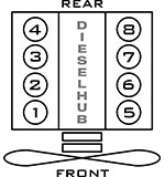
| Cylinder Numbers | Cylinders 1, 2, 3, and 4 are located on the passenger side bank Cylinders 5, 6, 7, and 8 are located on the driver side bank See cylinder numbers in figure 5 (below) |
|
| Engine Block Material | Compacted graphite iron (CGI) | |
| Cylinder Head Material | Aluminum alloy | |
| Injection System | Direct injection, high pressure common rail | |
| Fuel Injectors | 19 mm piezo electric fuel injectors with 8 hole nozzles | |
| Injection Pump | Bosch CP4.2 high pressure fuel injection pump | |
| Injection Pressure | 2011 - 2019 | up to 30,000 psi |
| 2020 - 2027 | up to 36,000 psi | |
| Aspiration | Turbocharged, intercooled with air-to-water charge air cooler (CAC) | |
| Turbocharger | See turbocharger model information by application type in the subsection below | |
| Reciprocating Assembly | • Forged steel crankshaft with shrink fit camshaft drive gear • Fractured cap connecting rods • Oil cooled pistons; internal passage integrated into the bottom of each piston allows oil to flow through and cool the top of the piston • Aluminum pistons on 2011 - 2019 model year engines, short skirt steel pistons on 2020+ engines |
|
| Valvetrain | Overhead valve, conventional pushrod cam-in-block • 4 valves per cylinder; 2 exhaust valves, 2 intake valves (32 valve) • Gear driven camshaft • Stamped steel rocker arms • Patented roller camshaft followers with hydraulic valve lash adjusters |
|
| Valve Lash | Service-less self-adjusting hydraulic lifters | |
| Cold Start Aids | Ceramic glow plugs, 1 per cylinder | |
| Cooling System | Dual cooling system with mechanical thermostat assembly; primary cooling system operates at high temperatures, secondary cooling system operates at significantly lower temperatures. | |
| Engine Oil Capacity | 2011 - 2022 pickup/cc | 13.0 quarts with filter change |
| 2023 - 2027 pickup/cc | 15.0 quarts with filter change | |
| 2015 - 2022 F-650/F-750 | 15.0 quarts with filter change | |
| 2023 - 2027 F-650/F-750 | 17.0 quarts with filter change | |
| Engine Oil Spec | 10W-30 engine oil preferred for normal use 5W-40 or 15W-40 engine oil is recommended for severe duty conditions Viscosity selection will depend on ambient temperature Synthetic engine oil recommended; see 6.7L Power Stroke engine oil viscosity chart for additional details |
|
| Oil Pump Type | Gerotor type oil pump mounted in front engine cover | |
| Lube Oil Filter | Motorcraft FL-2124S | |
| Fuel | Ultra low sulfur diesel (ULSD), maximum B20 biodiesel blends | |
| Power | 300 - 500 horsepower; see full model and model year breakdown in section below | |
| Torque | 660 - 1,200 lb-ft; see full model and model year breakdown in section below | |
| Idle Speed | 625 - 650 rpm on average; idle speed may vary based on conditions that include engine temperature, regeneration status, and electrical system demands | |
| Emissions Equipment | • Cooled exhaust gas recirculation (EGR); two stages of cooling before gases are recirculated, EGR metering valve positioned at inlet of EGR cooler • Diesel oxidation catalyst (DOC) • Selective catalytic reduction (SCR), requires diesel exhaust fluid (DEF) • Diesel particulate filter (DPF); silicon carbide substrate |
|
| B10 Life | 500,000 miles (800,000 km) [1] | |
| B50 Life | Not specified or rated | |
| Engine Weight | Approximately 1,100 lbs wet, 990 lbs dry | |
| Engine Dimensions | Length | 44.4 inches (112.7 cm) |
| Width | 33.3 inches (84.6 cm) | |
| Height | 33.7 inches (85.6 cm) | |
| Coupled Transmissions | 2011 - 2019 pickup/cc | Ford TorqShift 6R140 six speed automatic |
| 2020 - 2027 pickup/cc | Ford TorqShift 10R140 ten speed automatic | |
| 2015 - 2023 F-650/F-750 | Ford TorqShift 6R140 six speed automatic | |
| 2024 - 2027 F-650/F-750 | Ford TorqShift 10R140 ten speed automatic | |
[1] - Based on testing with 330 horsepower, 850 lb-ft commercial grade engine
Turbochargers by Application
2011 - 2014 Pickup Trucks
Garrett SST3266V "DualBoost" single sequential turbocharger
- Twin compressor, single turbine design (compressor wheels mounted to a single common shaft)
- Variable geometry turbine housing (variable nozzle, variable vane)
- Hydraulic VGT actuator
- Vacuum operated wastegate (PCM controlled via vacuum solenoid)
- Water cooled via primary cooling system
- Ceramic ball bearing design
2015 - 2019 Pickup Trucks
Garrett GT3788V single variable geometry turbocharger
- Variable geometry turbine housing (variable nozzle, variable vane)
- Hydraulic VGT actuator
- Non-wastegated
- Water cooled via primary cooling system
- 2015 to 2019 turbochargers are of the same model, but with different oil supply line and turbo pedestal; 2015-2016 turbos not directly cross-compatible with 2017-2019 turbos
2020 - 2024 Pickup Trucks
Ford LC3Z-6K682-A single variable geometry turbocharger
- Variable geometry turbine housing (variable nozzle, variable vane)
- Electronically actuated VGT position
- Ball bearing design
- Water cooled via primary cooling system
2011 - 2016 Chassis Cabs
Garrett AVNT3276V single variable geometry turbocharger
- Variable geometry turbine housing (variable nozzle, variable vane)
- Hydraulic VGT actuator
- Non-wastegated
- Water cooled via primary cooling system
2017 - 2019 Chassis Cabs
Garrett GT3582V single variable geometry turbocharger
- Variable geometry turbine housing (variable nozzle, variable vane)
- Hydraulic VGT actuator
- Non-wastegated
- Water cooled via primary cooling system
- Ball bearing design
2020 - 2024 Chassis Cabs
Ford LC4Z-6K682-A single variable geometry turbocharger
- Variable geometry turbine housing (variable nozzle, variable vane)
- Electronically actuated VGT position
- Ball bearing design
- Water cooled via primary cooling system
2015 - 2023 F-650 & F-750
Garrett GT3582V single variable geometry turbocharger.
- Variable geometry turbine housing (variable nozzle, variable vane)
- Hydraulic VGT actuator
- Non-wastegated
- Water cooled via primary cooling system
- Ball bearing design
Horsepower & Torque by Application
Super Duty Pickup Trucks
| Model Year(s) | Horsepower (hp @ rpm) |
Torque (lb-ft @ rpm) |
|---|---|---|
| 2011[2] | 390 @ 2,800 | 735 @ 1,600 |
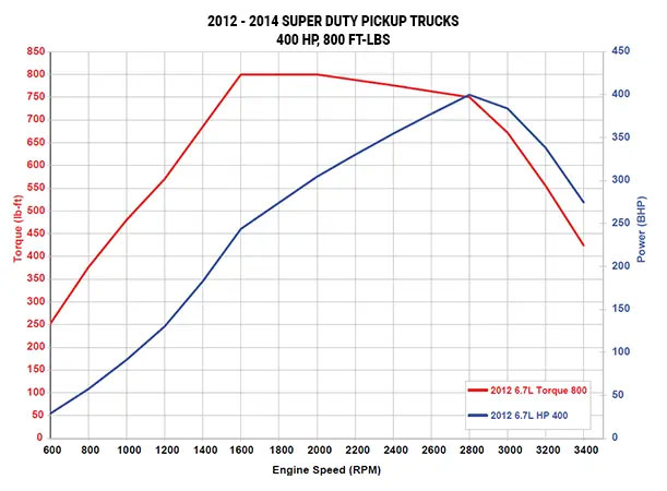
| 2011 - 2014 [2] | 400 @ 2,800 | 800 @ 1,600 |
| 2015 - 2016 | 440 @ 2,800 | 860 @ 1,600 |
| 2017 | 440 @ 2,800 | 925 @ 1,800 |
| 2018 - 2019 | 450 @ 2,800 | 935 @ 1,800 |
| 2020 - 2026 | 475 @ 2,800 | 1,050 @ 1,800 |
| 2023 - 2026 Standard Output | ||
| 2023 - 2026 High Output [3] | 500 @ 2,600 | 1,200 @ 1,600 |
| 2027 |
[2] - Ford Motor Company issued a free dealer PCM reflash for early engines that increased horsepower and torque to the 2012 figures.
[3] - High output engine standard beginning in 2027, no longer an optional upgrade
Super Duty Chassis Cab & Medium Duty Trucks
| Model Year(s) | Horsepower (hp @ rpm) |
Torque (lb-ft @ rpm) |
|---|---|---|
| 2011 - 2016 Super Duty | 300 @ 2,800 | 660 @ 1,600 |
| 2017 Super Duty | 330 @ 2,800 | 750 @ 1,600 |
| 2018 - 2019 Super Duty | 330 @ 2,600 | 750 @ 1,600 |
| 2020 - 2022 Super Duty | 330 @ 2,600 | 825 @ 1,600 |
| 2023 - 2027 Super Duty | 330 @ 2,200 | 950 @ 1,800 |
| 2015 - 2023 F-650, F-750 [4] | 270 @ 2,400 300 @ 2,600 330 @ 2,600 |
675 @ 1,600 700 @ 1,600 725 @ 1,800 |
| 2024 - 2025 F-650, F-750 [4] | 270 @ 2,400 300 @ 2,600 330 @ 2,600 |
700 @ 1,600 725 @ 1,600 750 @ 1,800 |
| 2026 - 2027 F-650, F-750 [4] | 270 @ 2,400 300 @ 2,600 330 @ 2,600 |
800 @ 1,600 825 @ 1,600 850 @ 1,800 |
[4] - F-650 and F-750 medium duty trucks available in one of three output ratings ranging from 270 to 330 horsepower; the 270 horsepower rated engine is standard
2011 Power Increase
The 6.7L Power Stroke diesel was originally launched at ratings of 390 horsepower and 735 lb-ft of torque. On August 3rd, 2010 Ford Motor Company announced that horsepower and torque ratings for the 6.7L Power Stroke diesel had been raised to 400 horsepower and 800 lb-ft of torque. Owners of the 390 horsepower model engines were able to receive a free PCM calibration upgrade to the new power figures. These actions were Ford's response to General Motor's announcement of performance figures for the next generation 6.6L Duramax LML, (397 hp, 765 lb-ft of torque); the Power Stroke's performance bump maintained Ford's position as the segment leader in power and torque ratings, while making a positive impression on new Power Stroke diesel owners.
Horsepower & Torque Curves
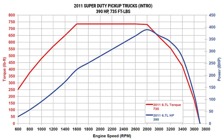
Image courtesy Ford Motor Company
Includes 2011 model year engines that received the free dealer upgrade
Image courtesy Ford Motor Company
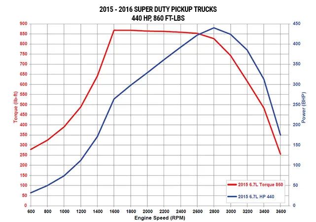
Image courtesy Ford Motor Company
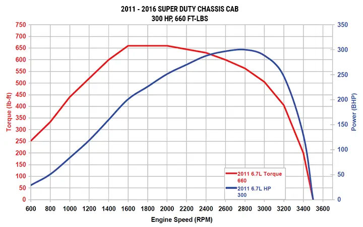
Image courtesy Ford Motor Company
High Output Engine
Ford Motor Company officially opened orders for the 2023 Ford Super Duty on October 27th, 2023, revealing that the new High Output 6.7L Power Stroke produced a peak 500 horsepower and 1,200 lb-ft of torque. The high output engine became standard for in all Super Duty pickup trucks for the 2027 model year.
The high output variant is available in F-250, F-350, and F-450 Super Duty pickup trucks in both single rear wheel and dual rear wheel configurations. Its massive torque numbers far surpass any competitor in the segment. In addition to a more aggressive engine calibration, the high output engine is equipped with stainless steel exhaust manifolds and utilizes a turbocharger with a water-jacketed compressor housing.


Editor, Diesel Hub